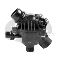
Thermostats are the watchdog of the engine’s cooling system, as they (i) constantly monitor the temperature of the coolant and (ii) accurately regulate the coolant flow through the radiator in order to obtain and maintain the optimum engine operating temperature.
This ensures an efficient combustion process – one that results in lower greenhouse gas emissions. In what follows, we focus on a particular type of thermostats: the electrically controlled or map-controlled thermostats. We list the thermostat parts, we explain how they work as well as how to deal with electrical or mechanical failures.
Thermostat elements
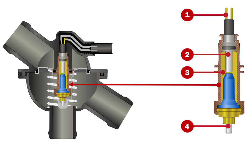
Before we go into how map-controlled thermostats work, you should be aware of the position of their four main parts:
- Electrical pin
- Resistance heating in wax element
- Wax element
- Expansion element
Map-controlled thermostats: two temperature ranges
Electrically controlled thermostats generally operate within two working temperature ranges, depending on the engine load requirements: low to medium load versus high load or high speed. The thermostat is not activated until a temperature threshold is crossed and the coolant temperature is just below the setpoint.
- With a low or medium load on the engine, map-controlled thermostats work exactly like traditional thermostats, submerged in coolant inside the thermostat housing, but they start to open at a higher temperature range (between 100°C and 110°C, depending on the exact thermostat operating range). This enables a more efficient combustion process and ensures that lower levels of carbon monoxide and hydrocarbon are released into the atmosphere.
- When the engine management unit detects an increase in engine load or – on some vehicles – when the sports mode is activated, energy is applied to the heating element. The latter is in contact with the wax element and causes the thermostat to open earlier, in order to maintain a lower temperature in the coolant circuit (between 85°C and 95°C, again depending on the operating range of the thermostat in question). This temperature drop improves the density of the air entering into the engine’s combustion chambers, thus enhancing engine performance and preventing engine overheating during high-performance operating cycles.
Note that the driver is unaware of the temperature changes: modern vehicles keep the temperature gauge needle on the instrument panel stable as long as the temperature is within the operating range. The optimum operating temperature for a vehicle is stored on maps in the engine management unit and is based on the load on the intake system, the speed and temperature of the vehicle.
The electronic control unit constantly compares the temperature stored on the map to the actual temperature of the engine. Based on this information, it sends a certain pulse-width modulation signal (or PWM signal) to the heating element of the thermostat, controlling it and ensuring it will remain open until the required temperature is reached. A PWM that is low (without voltage) corresponds to a high coolant temperature, and a PWM that is high (with voltage) corresponds to a low coolant temperature. The PWM signal – also referred to as the Square Wave signal – is very precise in delivering the exact amount of energy to the heating element due to its duty cycles: controlled intervals of switching on and off.
If the engine temperature is high, additional actions may be required to quickly lower the coolant temperature. The control unit can, for instance, start the electric fans. Vehicles with an electric water pump like the Gates 41504E (as in BMW vehicles that use an electric water pump as their main water pump) can also automatically increase the coolant flow.
Thermostat failure: electrical and mechanical
Electrical thermostat failures are detected by the control unit and generate a fault code in this unit’s memory. Before performing a thermostat replacement because of a fault code, it is best to check the electrical wiring between the engine management unit, the thermostat and the power supply cable, to avoid replacing a part that is working properly. Use a multimeter to measure resistance, and check the wiring with the help of the wiring diagram or the diagram of the vehicle. That way, you know where current for the thermostat heating element comes from and which cables you should focus on.
Moreover, when a component related to the thermal management system fails, the control unit may take a replacement value, for instance activating the fan or the thermostat resistance just to be on the safe side. So again, before carrying out any repairs, check whether the rest of the components involved – such as the temperature sensors – are working as they should.
Lastly, the mechanical failures of these thermostats are the same as with traditional thermostats. You can find them in the Thermostat Failure Signs Guide.