The theoretical 4-stroke engine operating cycle consists of the intake stroke, the compression stroke, the power stroke and the exhaust stroke. For the sake of simplicity, the same theoretical cycle is used for all automotive engines. But to make sure every cylinder is filled with and emptied of gases in the most efficient way possible at each specific moment (even at different speeds and with different loads), the angle at which the valves open and close has to diverge from the theoretical cycle. This is where the VVT or variable valve timing system and VVT solenoids come in. Read on to discover the function and geometry of these important parts.
Delay and inertia
As explained in the introduction, the valve opening and closing times have to differ slightly from the theoretical cycle in order to optimise the process of gases entering into and escaping from the cylinder. And that, in turn, is affected by both delay and inertia:
- Delay:
Valves don’t open instantly. It can take between 20-30° of crankshaft rotation for them to be completely open. Without any corrective actions, this would cause delays in both the intake cycle and the exhaust cycle:
- if, in the intake cycle, the piston starts to descend and the intake valve is not yet open due to the above-mentioned delay, a vacuum is created in the cylinder. This makes it more difficult for the piston to start its downward stroke and therefore reduces engine performance.
- in turn, if the piston starts its upward movement in the exhaust cycle, and the valve is not open due to the delay, the pressure in the cylinder opposes the rise of the piston, again reducing the performance of the engine.
- Inertia:
Moreover, when a valve opens, the gases slightly ‘hesitate’ to start moving. This also generates a short delay at the beginning of the process (the cylinder filling or emptying).
Standard valve opening without a VVT system
The following graph shows the fixed geometry of a vehicle without a variable valve timing system (VVT system), and where T.D.C. refers to top dead center and B.D.C. to bottom dead center:
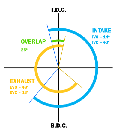
Standard valve opening diagram without VVT system
- IVO or Inlet Valve Open (in blue)
In order to avoid a delay and thus allow the intake gases to enter the cylinder as soon as possible, the intake valve is opened a little before T.D.C.
- IVC or Inlet Valve Closed (in blue)
The intake valve closes a little after the piston has passed B.D.C. This way, advantage is taken of the inertia of the gases, thereby optimizing the process of filling the cylinders.
- EVO or Exhaust Valve Open (in orange)
At the end of the downward stroke, although the pressure inside the cylinder has decreased as the gases have pushed the piston downwards, to ensure that the piston does not meet any opposition during its upward stroke, the exhaust valve opens before B.D.C.
- EVC or Exhaust Valve Closed (in orange)
To make sure that all the burned gases have been ejected and the air remaining in the cylinder is completely fresh, the closing of the exhaust valve is delayed a little.
As you can see in the diagram, there is an overlap (in green): a short period during which the intake and exhaust valves are open at the same time.
The VVT system or variable valve timing system
The function of VVT system
Since the speed of automotive engines is not constant, the timing diagram should ideally vary with it. In other words: the valve closing and opening angles should be adapted to values that maximise the processes of cylinder emptying and filling, according to the engine speed.
The VVT system influences the timing of the valves with the help of a phase shifter located at the head of the camshaft. This part is activated by the engine control unit by means of oil flow controlled by the solenoid valve.
The main advantages of this system are:
- reduced fuel consumption
- increased torque and power
- reduced emissions
Mainly in petrol engines
The VVT system was introduced in Asian and European vehicles in the late 80s and early 90s. In the mid 2000s, this system became more popular and started to be used by all the main car manufacturers. Nowadays, this system is normally installed in petrol engines (though not in all), but can also be found in some diesel engines. While actual name used for the system varies from manufacturer to manufacturer, and, although there may be small differences, the principle of operation is practically the same:
- Honda: VTEC
- Toyota: VVT-i
- BMW: VANOS
- Ford: Ti-VCT
- Kia-Hyundai: CVVT
- Porsche: VARIO CAM
- VAG: TGV
- …
Solenoid valve and other VVT components
The main components of a variable valve timing system are:
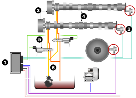
The main components of a VVT system
- ECU
- Rev sensors
- Cam phaser
- Camshafts
- Solenoid valves
- Oil line
Zooming in on the cam phaser
The cam phaser adapts the angle at which the valves open. It consists of the following parts:
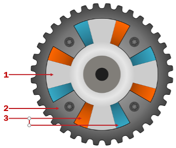
The components of a cam phaser
- Inner rotor: this part is attached to the camshaft.
- Outer housing: this part is attached to engine timing sprocket.
- Galleries: these are actively filled with oil on one side or the other of the inner rotor blades. This rotates the inner rotor relative to the outer housing, advancing or retarding the times at which the valves open.
Now, this oil flow to one side or the other of the galleries is controlled by the solenoid valve. As we shall see later in this article, the solenoid valve allows the oil to flow through the pipes to the galleries according to the pulse width modulated signal (PWM) it receives from the control unit.
Zooming in on the solenoid valve
The solenoid valve, in turn, consists of the following parts:
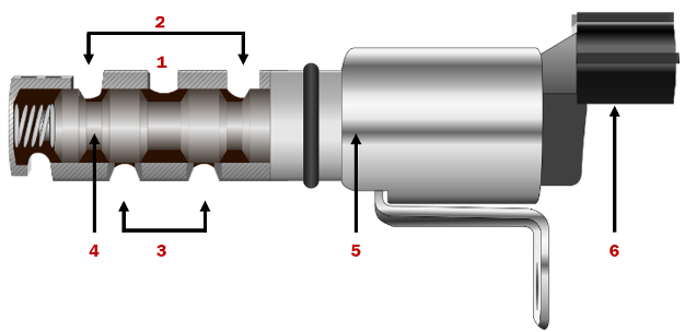
The components of the solenoid valve
- Oil supply line
- Oil return
- Oil lines to camshaft
- Piston
- Solenoid coil
- Electrical connector
The solenoid valve: positions
The VVT system is most commonly installed to operate with the intake camshaft, although in some vehicles you can also find one associated with the exhaust camshaft. High-performance engines, for instance, work with more complex systems capable of varying the lift of the cams. Thus solenoid valves may be found in several different locations.
1. Solenoid in ‘retard’ position
The solenoid can be in the ‘retard’ position:
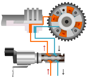
The solenoid in ‘retard’ position
When the engine is idling, the solenoid valve moves its internal plunger. This allows oil to flow through to fill one side of the galleries, while it allows oil to return to the sump from the other sides. The result is they will open a little later in the engine cycle.
Delaying the opening of the inlet valve prevents burnt gases from entering the intake manifold at idle speed. It also saves fuel: the engine can continue to run smoothly, without the idle speed having to be raised.
2.Solenoid in ‘advance’ position
The solenoid can also be in ‘forward’ position:
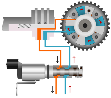
[image6] The solenoid in ‘forward’ position
At high engine speeds, the solenoid moves to the opposite position. This reverses the oil flow and causes the camshaft to move to its maximum ‘advanced’ position.
When the engine is runing at high rpm, the cylinder takes much less time to fill up. So, if we advance the opening of the valve, we make sure that inlet gas begins to enter the cylinder even before the piston has reached T.D.C. By advancing the opening, the closing is also advanced, of course. But in this case, due to the engine speed, the cylinder still has time to fill up enough, guaranteeing optimum performance and taking advantage of the inertia of the gases circulating at higher speeds.
3.Solenoid in ‘on hold’ position
Furthermore, the solenoid can also be in the ‘on hold’ position:
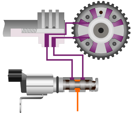
The solenoid in the ‘on hold’ position
The camshafts have Hall sensors. These sensors tell the control unit their exact position with respect to the crankshaft. This way, the control unit can determine the position of the solenoid valve that is required at each moment. It calculates this by comparing input signals (such as engine speed, throttle position, etc.) with the maps it has memorised. When the desired advance is reached, the solenoid is placed in the on hold position. Thus, it blocks the oil flow in both directions, in turn holding the camshaft at a certain angle relative to the camshaft sprocket.
When the engine is running at an intermediate speed or in other specific situations, the control unit can determine an ‘intermediate advance’ position of the camshaft for optimal engine operation at that time. The intermediate positions help reduce NOx levels and hence have a similar effect on the engine as do exhaust gas recirculation systems (usually installed in diesel engines, EGRs let some exhaust gas back into the intake manifold. When they re-enter the combustion chamber, they lower the temperature and this results in generating less NOx).
VVT system failures
Oil pressure problems
The most common hydraulic failure is low or no oil pressure. This is frequently the result of oil that is not been properly maintained carrying debris and sludge. When these impurities are deposited in the pre-filter of the oil feed channel of the solenoid valve, they restrict the oil flow. This causes the system to operate slowly or not at all. Furthermore, the particles may pass through the filter, causing the solenoid valve to seize in any of its positions.
The problem of too little pressure can be exacerbated if the oil does not have the correct viscosity, or in the case that there is another failure in the lubrication system.
Oil pressure problems
Electrical failures
Solenoid valves can also experience electrical failures. The coil may fail, causing the valve to stop working. As always, though, checking the cables that go to the valve is good practice to avoid unnecessarily replacing a part that is in good condition.
The engine control unit uses the camshaft and crankshaft position sensors to evaluate the operation of the system. In the event of an abnormality, it generates a fault code and turns on the engine diagnostic light.
[image9] Engine diagnostic light