As an experienced mechanic, you may be tempted to check belt tension by rule of thumb, thinking that turning the belt through 90 degrees suffices to determine whether its tension is okay. The sonic belt tension tester STT-1 provides you with just one single tool to measure belt installation tension accurately every time, thus providing a quality standard for timing and Micro-V® belts with manual tensioners.
Belts you can check with the STT-1
Proper belt tension is essential for optimum performance, service life and reliability, both for timing and Micro-V® belts. Fortunately, checking tension is easy with the STT-1, which relies on microphones and frequencies to check the correct amount of tension. A green light means you can rest assured that the amount of tension is correct, so you simply have to adjust the tensioner until a green light appears. The more challenging part may be telling the sonic belt tension tester which application you’re testing – but we will get to that shortly.
You can apply the sonic belt tension tester STT-1 to both timing and Micro-V® belts, providing they have fixed clamping systems. Checking belt drives with automatic tensioning systems is not possible.
-
When it comes to timing belt drives, you can only check the installation tension with STT-1 on newly installed belts. The tool cannot be used to check belts that have already been put into operation.
-
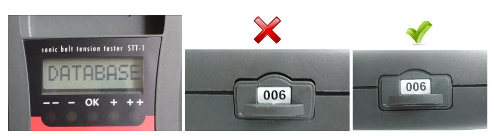
As of data chip number 006 (check the number on the side of your tension tester to find out which version you have), the sonic belt tension tester can be applied to Micro-V® belt drives as well. For those, it can be used to check both initial assembly tension and the tension of belts that have already been used.
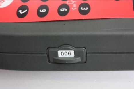
Data chip number 006, indicating the latest version of the device
Before using the STT-1: self-diagnosis
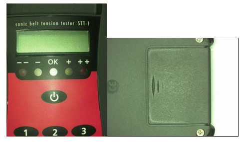
Before each use, the STT-1 device should run through a self-diagnosis process to ensure that the microphones are working correctly. To do this, press 999 on the keypad and then press Enter. There will be a slight humming noise from the measuring trough. Now put the measuring head containing the microphones into the recess and apply a little pressure to it. A green light should appear. Then turn the measuring head and check the other microphone. It is possible two red indicators light up first. In case the green indicator does not light up for both sides, the tool is faulty.
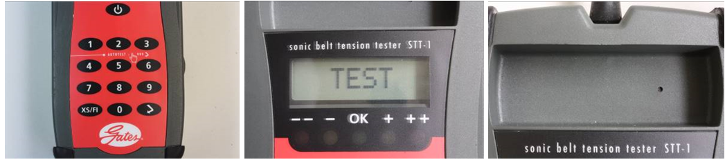
STT-1: self-diagnosis before use
Finding the right frequency
All the needed frequencies are stored on the STT-1’s data chip, thus enabling you to adjust nearly every belt to the correct tension. This prevents confusion and frees you from the time-consuming task of consulting lists and booklets to see which tension is correct for which belt/application. When using the STT-1, you simply have to enter the timing belt number. As of tension testers with data chip number 006, you may have to use a special code number instead. Both of these numbers can be found on the online Gates catalogue drawing (for more information on the code number, please consult technical bulletin 021 at Gates TechZone).
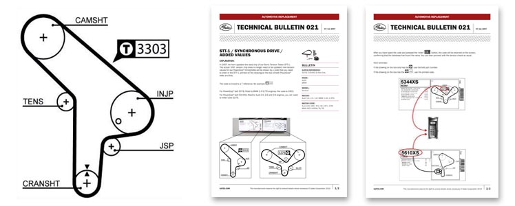
Technical bulletin 021
Measuring process for timing belts
When using the STT-1, the engine should be cold (i.e. at room temperature). The engine should be in the position prescribed by OE for changing the belt (usually Top Dead Centre).
-
Tension the belt.
-
Rotate the engine exactly two revolutions, unless otherwise indicated on the online Gates catalogue drawing.
-
Enter the timing belt number or the code number, using the keypad.
-
Press Enter.
-
If the chip contains the data in question, the number or code number will appear on the display.
However, some timing belts are used in completely different engines. To specify which application you are testing, enter 1, 2 or 3 after entering the belt number. In case of a non-XS belt (e.g. 5043), enter 5043, press the XS/FI button thrice, and press 1, 2 or 3, depending on the engine. (To find out if the application in question corresponds to a 1, 2 or 3: please check the online Gates catalogue drawing).
Now hold one of the microphones in the place marked by a on the online Gates catalogue drawing (on the outside or inside of the belt). Keep it close to the timing belt (at approximately ten millimetres distance) and gently pull the belt a couple of times like a guitar string to make it vibrate. Important: use only one of the microphones to measure the frequency! The other microphone serves to filter out any ambient noise, thus preventing incorrect measurements. The tool will ‘beep’ when a Hz value has been registered. Adjust the tension until the light turns green. If you hear no ‘beep’ at all, the applied tension diverges too much from the target.
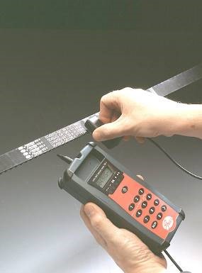
Hold the STT-1 at approximately 10 mm from the timing belt
Measuring process for Micro-V® belts
To ensure the most accurate results possible, the tension check should be done with the longest free belt span. The free span is the distance between the point where the Micro-V® belt starts to lose contact with the pulley and the point where the belt is in full contact with the next pulley. The free span length used to check the belt tension has to be measured very precisely. The Gates tape measure can be used for this purpose. If such a special tape measure is not available, you can use a standard tape measure.
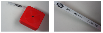
The Gates tape measure
Next, prepare the STT-1:
-
tap digit 8 (to switch the STT-1 to Micro-V® mode).
-
enter the length (in millimetres) you determined using the tape measure (if the length was less than 180 mm, enter 180. If it was more than 500 mm, enter 500).
-
press the XS/FI button twice, until FI appears on the display.
-
enter 1 for a new belt or 2 for a re-installed belt (same direction of rotation!).
-
press Enter.
Now the display shows the values you’ve entered, and the sonic belt tension tester is ready for use.
The measuring procedure itself is identical to that of the timing belt:
In this scenario as well, the second microphone filters out any ambient noise to ensure correct measurements.
Error messages
To conclude, we’ll walk you through some error messages that may appear on the display of your STT-1.
Error message 1
Error message 2
Error message 3